Guided-Wave Testing of H-Shaped Anchors and Buried Multisided Poles
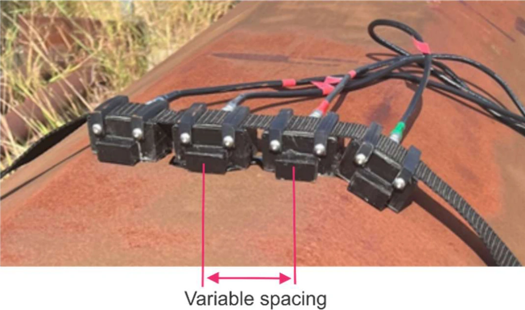
A four-segment MsT probe can be mounted on a flat anchor face or arranged around a multisided pole. The two examples below show how probe placement changes with the structure.
Buried H-shaped anchor
Three plate probes attached to an exposed face of the anchor collected full matrix capture data. The total focusing method (TFM) image showed several indications between about 1.0 and 3.4 ft. A separate reflection at about 4.6 ft identified the anchor end.
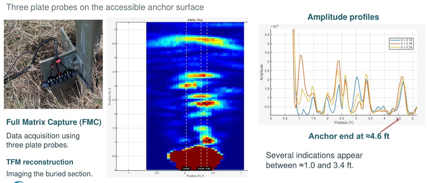
Sergey Vinogradov and Jay Fisher, Case Studies of Guided Wave Testing Using Magnetostrictive Transducer Arrays, ASNT Annual Conference, Columbus, Ohio, 2026. Complete presentation with corrected slide numbers · SwRI conference listing.
Buried multisided pole
On an octagonal pole, the segmented array sits on adjacent flat faces. The Verona paper shows how the spacing between segments accommodates the pole geometry.
Measurements on a retired pole show increasing wall loss toward the buried end. The 180 kHz image resolves moderate loss closer to the soil interface, while 64 kHz gives a stronger response from severe loss farther along the pole.
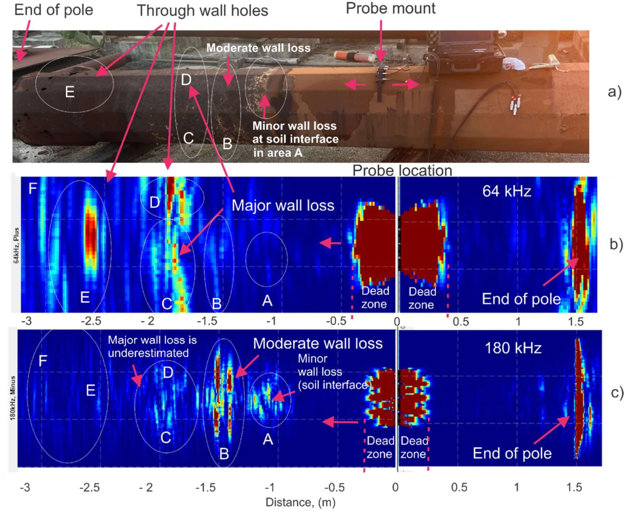
Sergey Vinogradov, Jay Fisher, Patrick Grädel, Pierre Dupuis, and Dominik Hirschhausen, Corrosion Mapping in Buried Section of Monopoles Using Magnetostrictive Transducer Arrays, ECNDT 2026, Verona, Italy. Published paper · CC BY 4.0. Figures excerpted from pages 4–5.