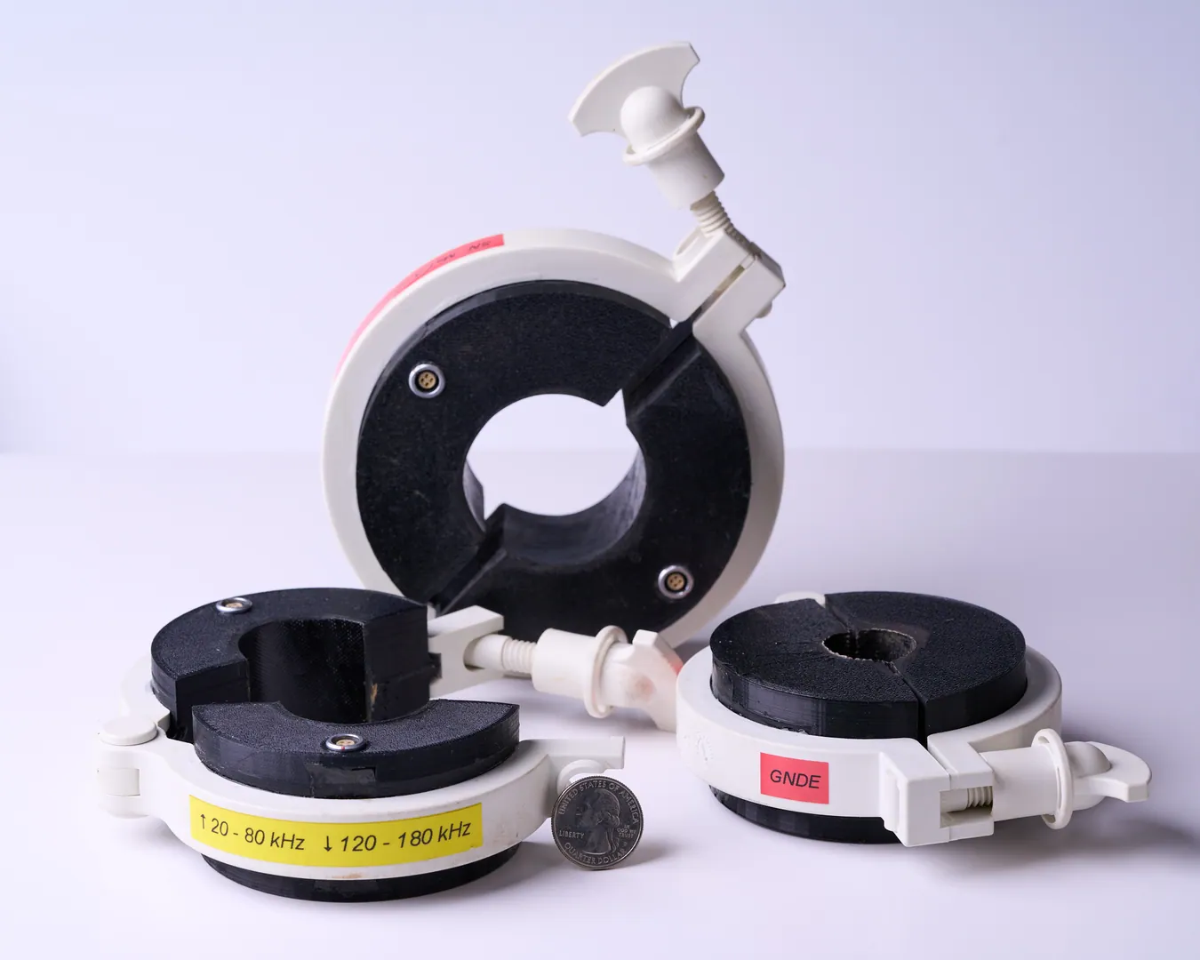
Split-Ring MsT Probes — Clamp-On Style
Frequency: 20–200 kHz 0.50–2.50 in diameter, in 0.25 in increments Instrument: MSS RV5
Installation clearance: Allow 1.5 in (38.1 mm) between the anchor rod and an adjacent structure.
Sensor configurations, application photographs, and technical specifications.
Guided-wave probes for corrosion screening of embedded pole sections, anchor rods and flat/H-shaped anchors. Six probe photographs with instrument and application specifications.
Frequency: 20–200 kHz 0.50–2.50 in diameter, in 0.25 in increments Instrument: MSS RV5
Installation clearance: Allow 1.5 in (38.1 mm) between the anchor rod and an adjacent structure.
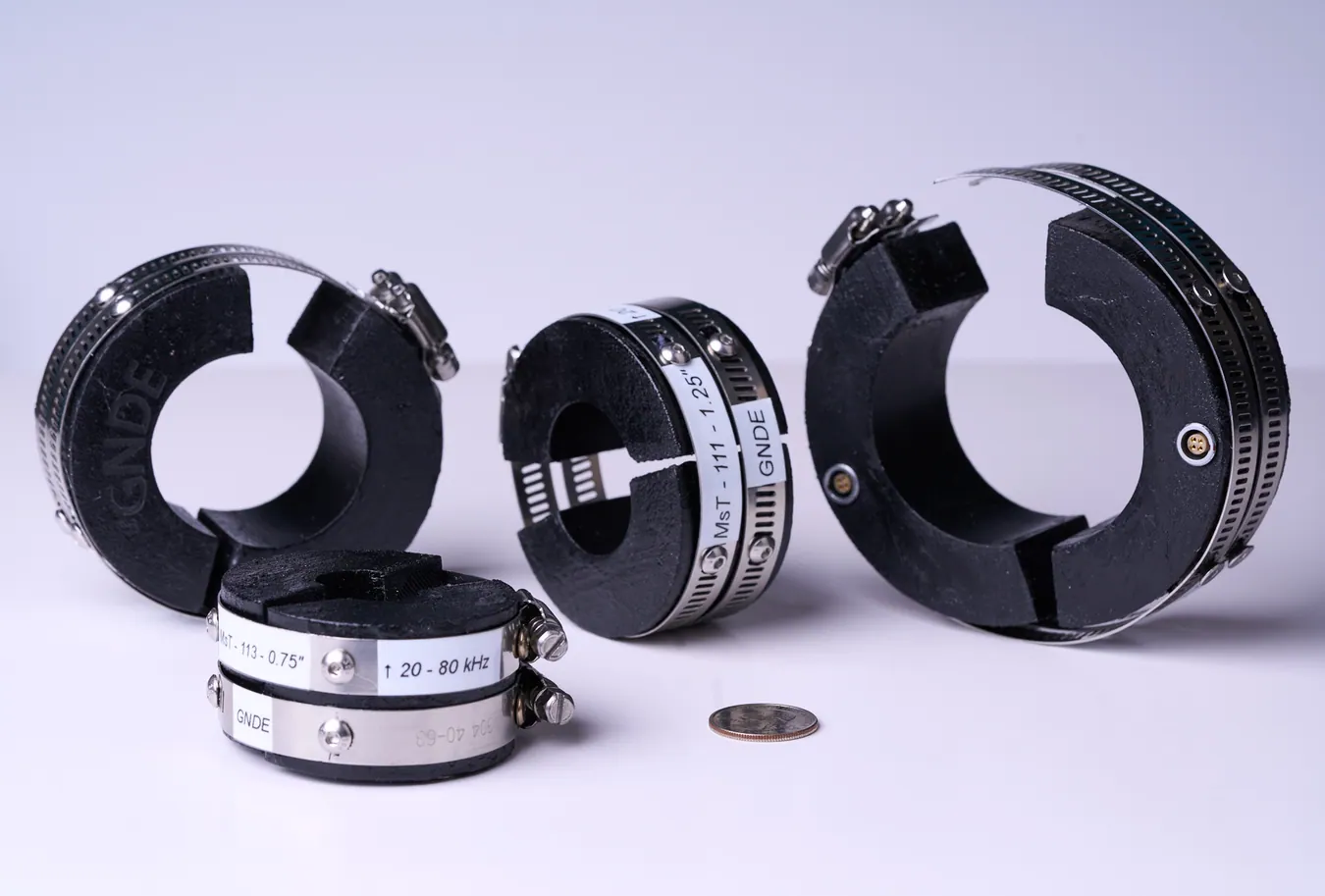
Frequency: 20–200 kHz 0.50–2.50 in diameter, in 0.25 in increments Instrument: MSS RV5
Installation clearance: Fits a 1 in (25.4 mm) gap between the anchor rod and an adjacent structure.
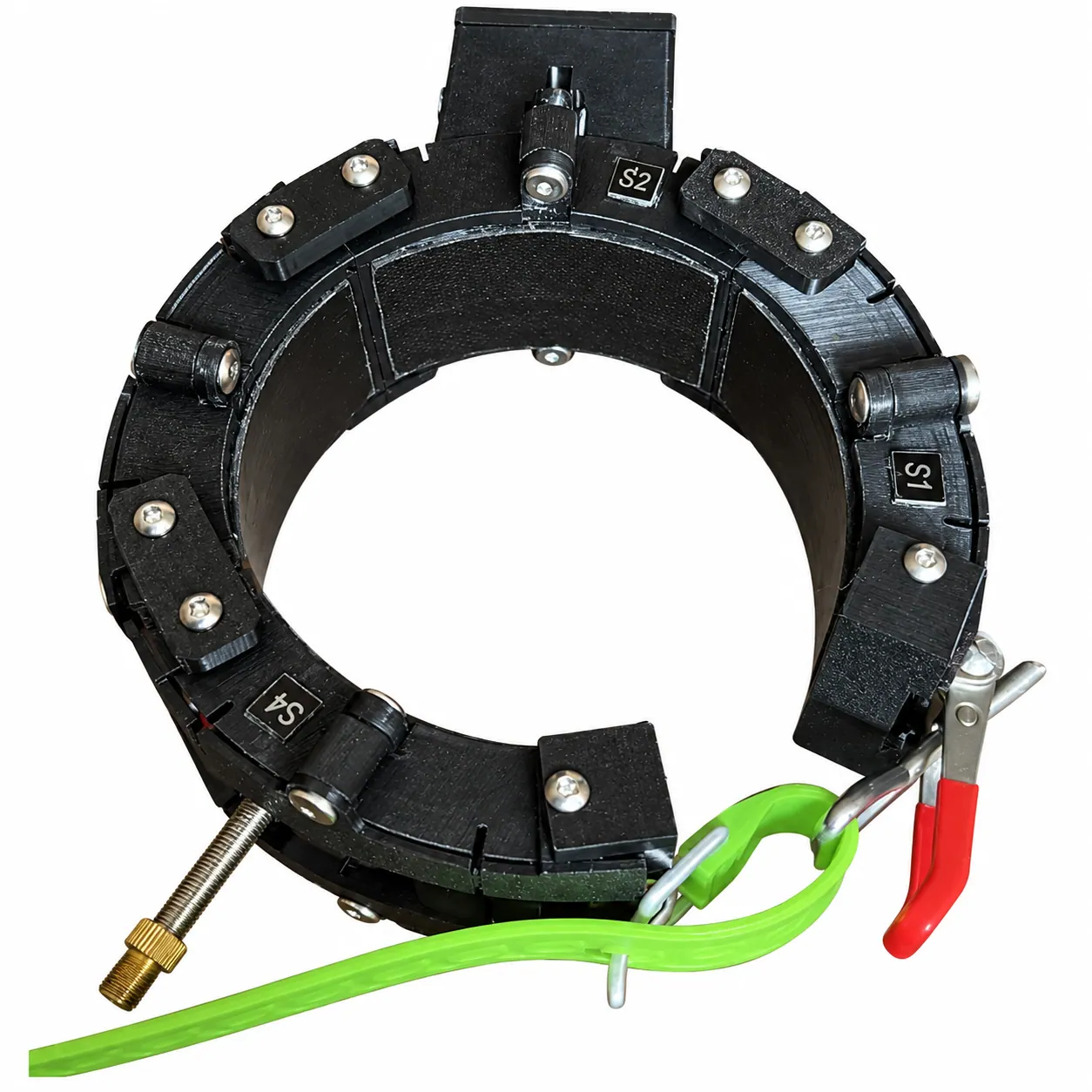
Frequency: 20–200 kHz For lighting poles 102–170 mm in diameter. Inflatable bladder conforms segments to the pole; suitable acoustic couplant improves coupling. Instrument: MSS RV5M · TFM imaging
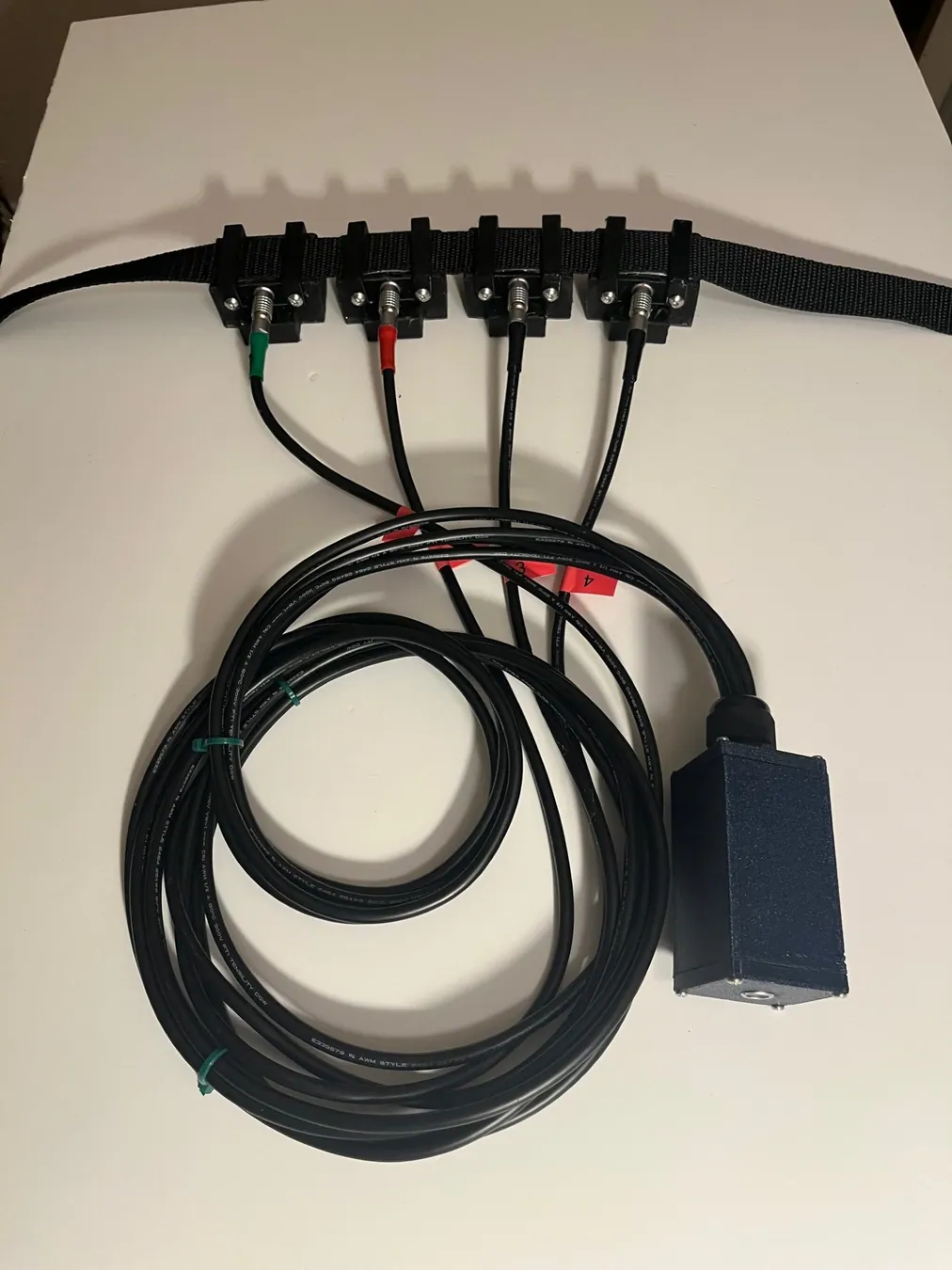
Frequency: 20–200 kHz. Segmented probe for flat anchors and buried multisided poles. Instrument: MSS RV5M · TFM imaging
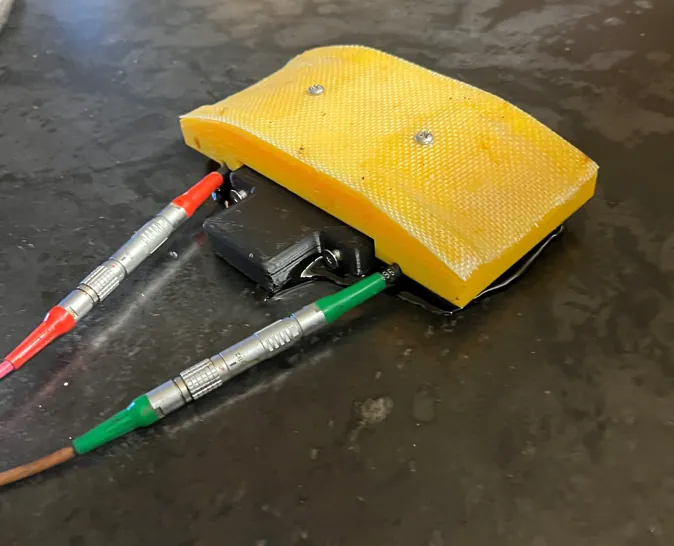
Frequency: 20–90 kHz 4-inch aperture for low-frequency inspection. Instrument: MSS RV5
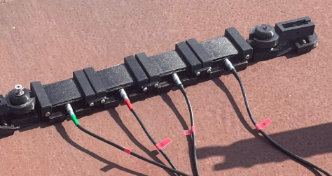
Four-segment MsT probe for flat anchors and multisided poles. Specifically designed for low-frequency inspection and particularly suitable for composite structures. Frequency range: 20–90 kHz. Combined aperture: 16 inches. Instrument: MsSRv5M. TFM imaging.
TFM capability: Multi-segment MsT probe configurations are used with the MsSRv5M instrument for TFM imaging. Single-segment and split-ring MsT probe designs use symmetric guided-wave interrogation with the MsSRv5 instrument.