Lighting Pole Inspection
Separate examples address lighting poles embedded in soil and concrete.
Lighting pole embedded in soil
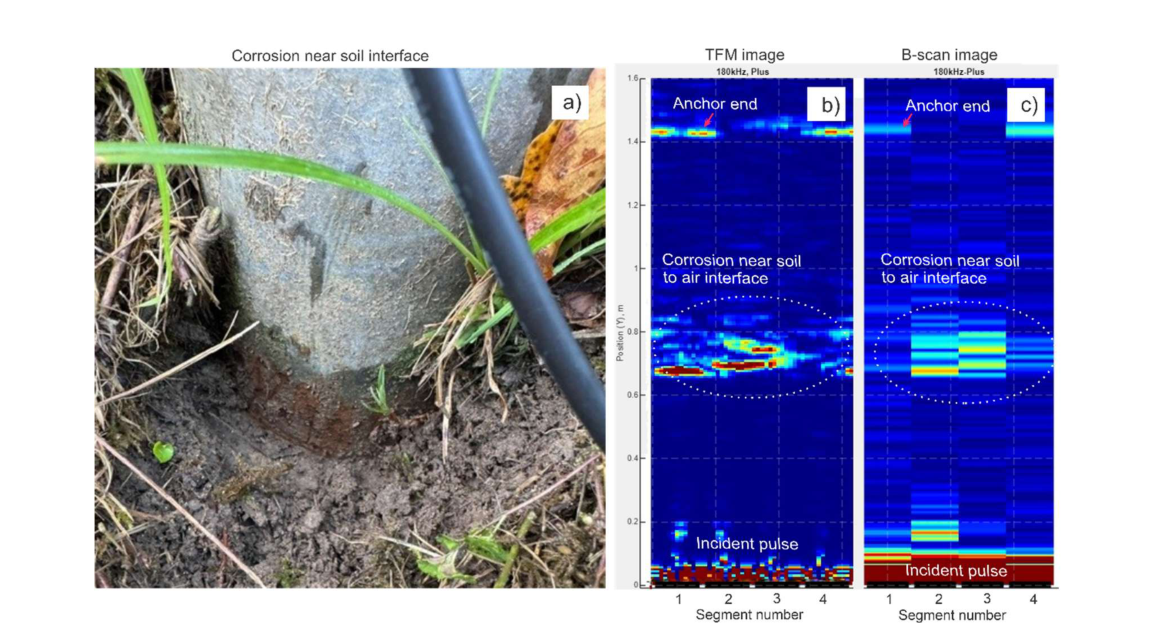
A four-segment MsT array inspected a 102 mm outside-diameter lighting pole. At 180 kHz, TFM showed the corrosion region near the soil line with greater spatial localization than the corresponding B-scan; the pole-end response remained visible.
Lighting pole embedded in concrete
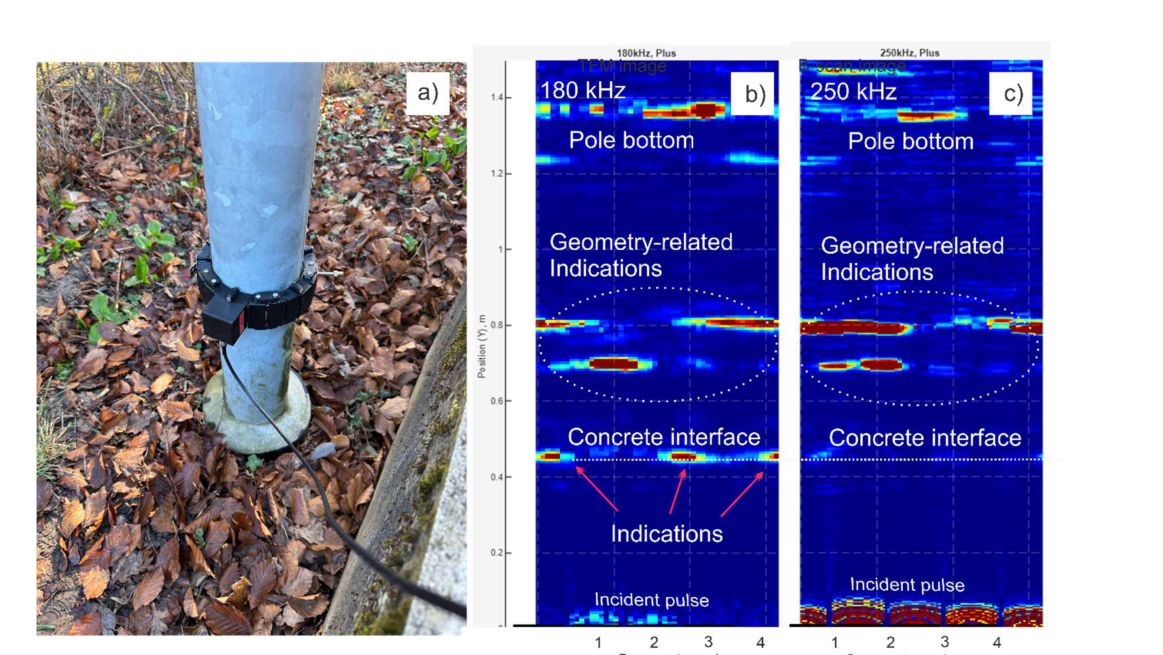
Measurements at 180 and 250 kHz demonstrated the influence of the steel–concrete interface on guided-wave reflections and attenuation. The strong interface response is not by itself evidence of corrosion.
Source and relevant pages
Vinogradov, S.; Fisher, J.; Grädel, P.; Dupuis, P.; Hirschhausen, D. Corrosion Mapping in Buried Section of Monopoles Using Magnetostrictive Transducer Arrays. 14th European Conference on Non-Destructive Testing (ECNDT 2026), Verona, Italy.
- Relevant pages
- PDF pages 6–8
- Figures
- Figure 4 (PDF page 6); Figure 5 (PDF page 7)
Page references use the PDF page positions, counting the first page as page 1. The page link requests the starting page; the complete paper remains available.
Unmodified article reproduced under Creative Commons Attribution 4.0. Copyright remains with the authors. The summaries on this page were prepared by GNDE.