Pipeline Inspection
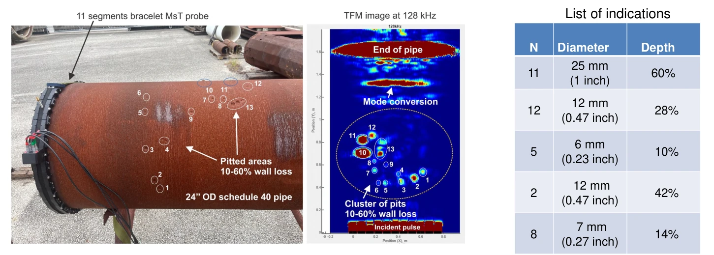
Guided-wave inspection of a buried, bitumen-coated pipe and TFM imaging of naturally formed corrosion pits in a pipe removed from service.
Buried pipe inspection
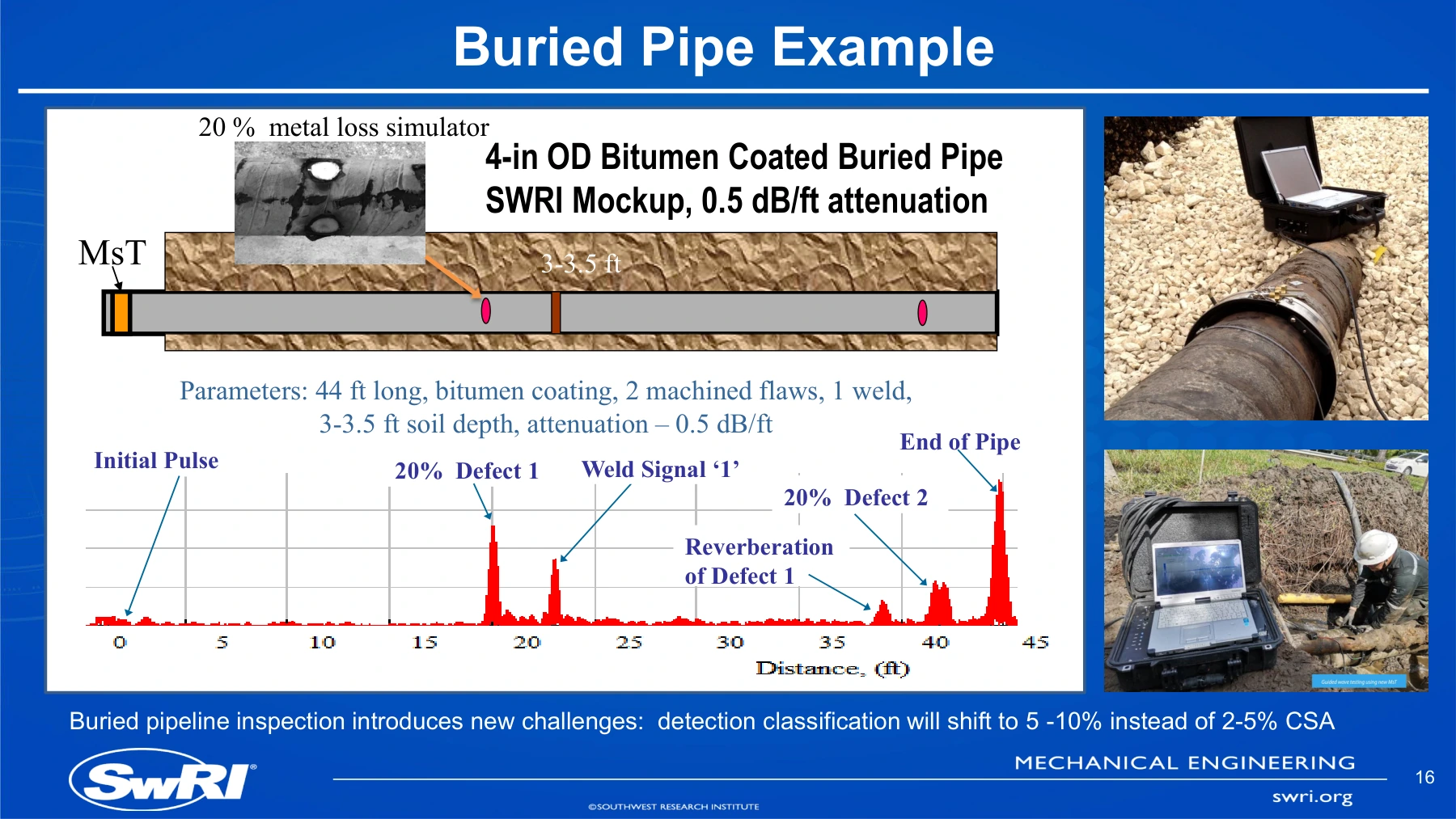
At SwRI, a 44 ft section of 4-inch OD pipe with a bitumen coating was buried under 3–3.5 ft of soil. The measured attenuation was approximately 0.5 dB/ft.
Transducer design. Sergey A. Vinogradov, “Magnetostrictive Transducer for Torsional Guided Waves in Pipes and Plates,” Materials Evaluation, vol. 67, no. 3, March 2009, pp. 333–341.
Naturally formed corrosion pits
A bracelet magnetostrictive transducer (MsT) array collected full matrix capture data. Total focusing method (TFM) processing localized clusters of naturally formed pitting in the pipe wall.
The paper reports pit depths from 10% to 60% of wall thickness. The example illustrates corrosion localization and relative screening; TFM image amplitude is not a direct measurement of remaining wall thickness.
Source for the pitting case
Vinogradov, S.; Akimov, N.; Cobb, A.; Fisher, J. Screening of Corrosion in Storage Tank Walls and Bottoms Using an Array of Guided Wave Magnetostrictive Transducers. Sensors 2026, 26(4), 1253.
- Relevant pages
- 13–14
- Figures
- Figure 13 (page 14)
- Section
- 7.1 — pipe section with naturally formed pitting
PDF page positions match the printed page numbers. The link opens the pitting results in Figure 13.
Unmodified article reproduced under Creative Commons Attribution 4.0. Copyright remains with the authors. The summaries on this page were prepared by GNDE.